

Vibration basics: amplitude, frequency and phase, and which sensor to trust
Every vibration signal is described by three things: how much, how often and in which direction. Knowing which to read, and with which sensor, decides whether the diagnosis is right.
The three things every signal tells you
| Quantity | What it answers | How it is shown |
|---|---|---|
| Amplitude | How much movement there is | Peak or peak-to-peak for displacement, peak or RMS for velocity and acceleration |
| Frequency | How often the movement repeats | Hertz, cycles per minute, or orders (multiples of shaft speed) |
| Phase | When the movement happens compared with another point or a once-per-turn mark | Degrees, only meaningful against a common reference |
Amplitude: displacement, velocity or acceleration
Displacement is the distance the part moves back and forth in one cycle, in micrometres or mils (0.001 inch), usually peak to peak. Velocity is how fast it moves, in mm/s or in/s. Acceleration is how hard it is pushed, in m/s² or g. The same movement gives very different readings in each unit, because higher frequencies give larger acceleration for the same displacement.
- Displacement favours low frequencies and slow machines. It shows how far the shaft really moves inside the bearing.
- Velocity is the best general measure of overall machine health across the middle range of frequencies.
- Acceleration favours high frequencies. Bearing impacts and gear mesh show up first here.
Frequency: the clue to the cause
Most faults repeat at a frequency tied to shaft speed: unbalance at 1×, misalignment at 1× and 2×, looseness at many multiples, gear mesh at the tooth count times shaft speed, bearing defects at their own non-integer orders. That is why the running speed must be known before any spectrum is read.
Phase: how the machine moves
Phase compares two signals at the same frequency. It is measured against a once-per-turn reference, usually a sensor looking at a keyway or a piece of reflective tape on the shaft. Two bearings moving in step (0° apart) or opposite (180° apart) means different faults. A phase reading on its own means nothing. It is useful only when compared with another reading.
Shaft or casing: choose the sensor to match the machine
A proximity probe is a non-contact sensor fixed to the bearing housing. It measures the shaft's movement relative to the housing. It is the right choice for machines with fluid-film bearings and a casing much heavier than the rotor, because the casing barely moves and hides what the rotor is doing. A casing sensor (accelerometer or velocity sensor) is the standard choice for machines with rolling bearings, where the vibration passes straight through the bearing into the housing.
Two probes at the same bearing
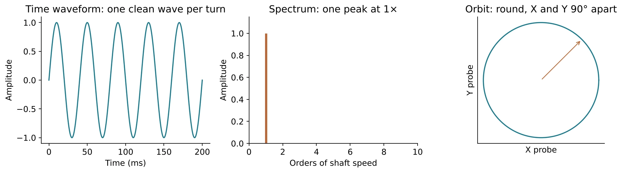
Two proximity probes are normally set 90° apart, usually at 45° either side of vertical. Together they draw the orbit, the path of the shaft centre. A third probe looking at the shaft end or a collar measures axial position. One fixed convention for naming the probes (for example the horizontal probe on a stated side when viewed from the driver) matters more than which convention it is, because phase and orbit direction are read from it.
Online systems and portable analyzers
An online protection system is wired to the control room, trips the machine at set levels and stores the trend. It is usually reserved for large critical machines. A portable analyzer taps the same signals, or uses its own sensor, and is used for frequency analysis, balancing and diagnosis. Most plants need both.