

Unbalance and field balancing: the signature and a one-plane worked example
Unbalance gives a clean 1× peak, a round orbit and 90° phase between the two probes. The balancing method that removes it is plain vector arithmetic.
What unbalance is
Unbalance is uneven mass around the rotor. The centre of mass does not sit on the axis of rotation, so every turn the rotor throws a rotating force into the bearings. The force grows with the square of speed.
How to recognise it
- Dominant 1× peak in the radial spectrum.
- Round orbit on a two-probe system.
- About 90° phase between the horizontal and vertical probes on the same bearing.
- Phase steady from run to run at the same speed.
Types of unbalance
| Type | What it means | How the phase looks |
|---|---|---|
| Static | The mass is offset along the whole rotor | Both ends move in step, 0° apart |
| Couple | Two equal masses at opposite ends, 180° apart | Both ends move in opposite directions, 180° apart |
| Dynamic | A mix of both, the usual case | Phase differs between the ends by an angle between 0° and 180° |
| Overhung | The mass sits outside the bearings | Strong radial and axial 1×, in step |
One-plane balancing by vectors
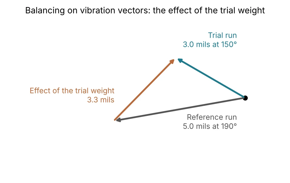
When the rotor is mainly static unbalance, one correction plane is enough. Run the machine and record the vibration amplitude and phase as the reference. Stop and fix a known trial weight at a known angle. Run again and record the new vibration. Subtract the two vibration vectors. What remains is the effect of the trial weight alone.
The calculation
- Effect of the trial weight = trial run vector minus reference vector.
- Correction weight size = reference amplitude ÷ effect amplitude × trial weight = 5 ÷ 3.3 × 75 ≈ 110 g.
- Correction angle comes from the same vector division: here about 354°, using the 30° trial weight as the starting angle.
- Remove the trial weight before fixing the correction weight, unless the sum is worked out with it left in place.
- Run again. If the level is still high, repeat with the new reading as the reference.
Check the convention
Whether the angle is measured with or against rotation, and whether the instrument reports phase lag or lead, changes the answer. Confirm the convention on a trial run, and always check that a small correct weight reduces the vibration. If the vibration is mostly 2× or axial, the cause is likely misalignment or a bent shaft, and balancing will not fix it.
A field example
A turbine-driven compressor could not reach full speed without tripping on high vibration at the bearing next to the coupling. The spectrum had a strong 1× peak, the orbit was a large circle and the two probes were 90° apart. All three pointed to unbalance. Balancing weights were fitted in the ten tapped holes around the coupling, using the same trial-run method, and the vibration fell afterwards. A coupling with tapped holes at set angles makes weights easy to place, and gives you exact angles to work with.